Key Takeaways
- Understand how hydraulic hose crimp fittings operate under high-pressure industrial systems
- Learn global standards (SAE, ISO, DIN) affecting crimp fitting performance
- Explore real industrial failure cases and maintenance lessons
- Compare crimp fittings with reusable, threaded, and clamp-style fittings
- Discover inspection cycles used in mining, construction, and oil & gas industries
- Review material engineering behind carbon steel, stainless steel, and plated fittings
- Learn predictive maintenance strategies to reduce downtime and cost
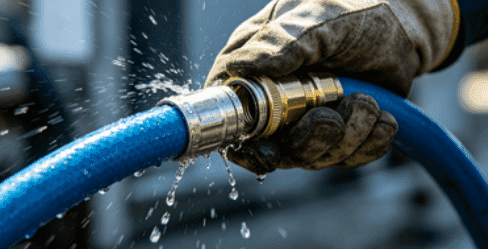
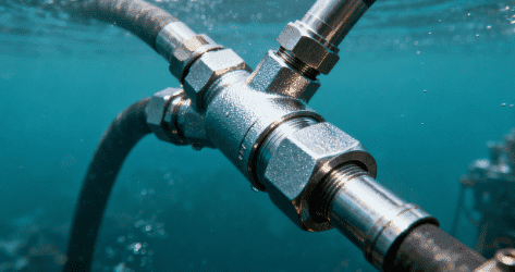
Hydraulic systems power modern industry—from excavators working on construction sites to offshore drilling rigs operating under extreme pressure conditions. At the center of these systems, hydraulic hose crimp fittings serve as one of the most critical connection technologies, ensuring fluid is transferred safely under pressures that can exceed 6000 PSI in heavy-duty applications.
According to industrial maintenance reports published by global fluid power associations, more than 35% of hydraulic system failures originate from hose connection issues rather than pumps or valves. Among these, improper maintenance of crimped fittings remains a leading cause.
Unlike reusable fittings, hydraulic hose crimp fittings are permanently deformed during installation. This creates a high-integrity mechanical bond between hose and fitting—but also means failure prevention depends heavily on maintenance practices, environmental conditions, and installation quality.
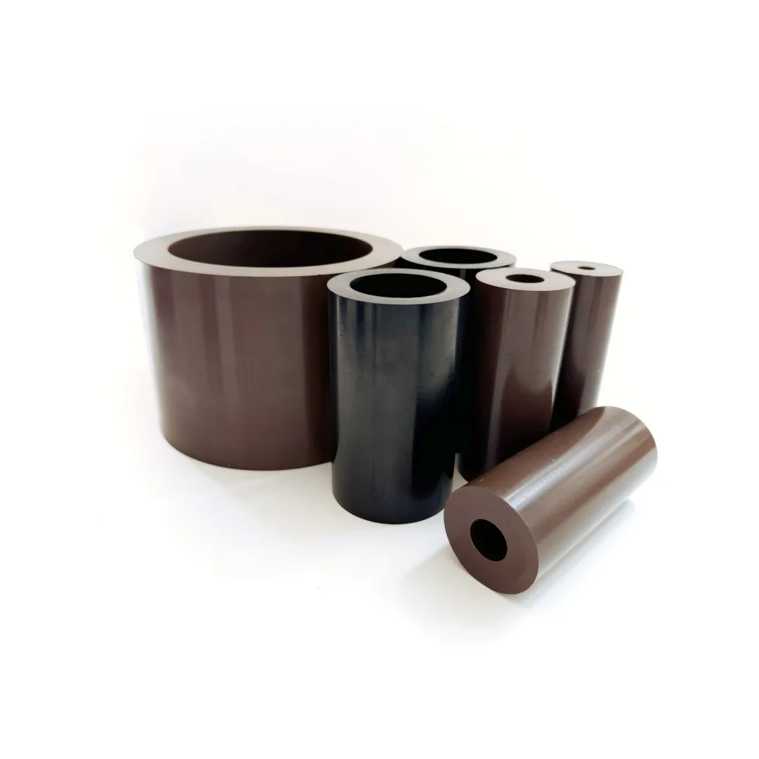
Companies such as Hebei Minglai Pipe Fitting Co., Ltd. specialize in producing high-precision hydraulic joints, PTFE tubing systems, and industrial crimp assemblies that meet international quality standards such as ISO 9001:2015 and pressure impulse testing protocols used in global hydraulic manufacturing.
Table of Contents
Global Engineering Standards for Hydraulic Hose Crimp Fittings

Industrial hydraulic systems follow strict international standards to ensure safety and compatibility.
SAE J517 Standard (Hydraulic Hose Classification)
The SAE standard defines pressure ratings and structural requirements:
- SAE 100R1: Single wire braid hoses
- SAE 100R2: Double wire braid hoses
- SAE 100R12: High-pressure spiral hoses
- SAE 100R14: PTFE hoses
Crimp fittings must match hose classification to ensure system integrity.
ISO 18752 Performance Standard
ISO 18752 categorizes hoses based on working pressure rather than construction type.
Key Engineering Insight:
This standard improves safety by ensuring hoses are selected based on actual operating pressure cycles rather than material alone.
DIN and EN Standards (European Systems)
DIN EN ISO standards define:
- Dimensional tolerances
- Burst pressure requirements
- Temperature resistance ranges
- Impulse cycle performance
Engineering Structure of Hydraulic Hose Crimp Fittings
Understanding the structure is essential for proper maintenance.
Ferrule Compression Zone
This is the most critical section where mechanical crimping occurs.
Concept Insight:
The ferrule deformation creates radial compression forces that lock the hose permanently in place.
Hose Bite Mechanism
The internal barb structure grips the hose lining.
Concept Insight:
This prevents axial pull-out under dynamic pressure fluctuations.
Sealing Interface
Sealing is achieved through:
- Elastomer compression
- Metal-to-metal contact (in high-pressure fittings)
- O-ring sealing (in specialized systems)
Industrial Failure Analysis of Crimp Fittings (Real Case Studies)
Case Study 1: Mining Equipment Hydraulic Line Failure
A mining operation in Australia reported repeated hose failures in excavator boom systems.
Root Cause Analysis:
- Excessive vibration near crimp area
- Incorrect hose routing causing flex fatigue
- Inadequate clamp support
Outcome:
After redesigning hose routing and adding vibration dampers, failure rate dropped by 62%.
Case Study 2: Chemical Plant Corrosion Failure
A chemical facility experienced leakage in stainless steel crimp fittings.
Root Cause:
- Exposure to chloride-rich environment
- Improper stainless grade selection (304 instead of 316L)
Engineering Lesson:
Material selection is critical in chemically aggressive environments.
Case Study 3: Construction Equipment Pressure Spike Damage
Hydraulic excavators in cold regions experienced sudden hose burst events.
Root Cause:
- Pressure spikes during low-temperature operation
- Rubber hose stiffening below -20°C
Hydraulic Hose Crimp Fittings Maintenance Framework
Predictive Maintenance vs Reactive Maintenance
| Maintenance Type | Description | Efficiency |
|---|---|---|
| Reactive | Fix after failure | Low |
| Preventive | Scheduled inspection | Medium |
| Predictive | Sensor-based monitoring | High |
Industry Trend:
Modern construction fleets are shifting toward predictive maintenance using IoT pressure sensors.
Inspection Standards for Hydraulic Hose Crimp Fittings
Weekly Inspection Protocol
- Visual leak detection
- Hose surface cracking check
- Fitting corrosion inspection
Monthly Engineering Inspection
- Pressure retention test
- Vibration stress analysis
- Temperature monitoring
Annual Full System Audit
- Full hydraulic circuit evaluation
- Hose replacement cycle analysis
- Crimp integrity destructive testing sample
Hydraulic Hose Crimp Fittings vs Alternative Connection Systems
| Feature | Crimp Fittings | Reusable Fittings | Threaded Fittings |
|---|---|---|---|
| Pressure Capacity | Very High | Medium | Medium |
| Installation Time | Fast | Medium | Fast |
| Reusability | No | Yes | Yes |
| Leak Resistance | Excellent | Good | Moderate |
| Industrial Use | Heavy machinery | Field repair | Low-pressure systems |
Engineering Insight: Why Crimp Wins in High Pressure Systems
Crimp fittings eliminate human error during tightening, which significantly improves sealing consistency under high pressure.
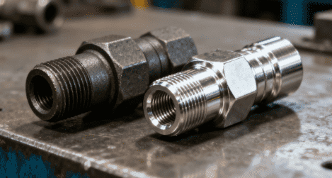
Material Science in Hydraulic Hose Crimp Fittings
Carbon Steel Fittings
Used in general industrial systems with protective coatings such as zinc plating.
Advantage:
High tensile strength and cost efficiency.
Stainless Steel 316L Fittings
Used in offshore, chemical, and marine applications.
Advantage:
Superior corrosion resistance in chloride environments.
Zinc-Nickel Alloy Coated Fittings
Emerging trend in industrial hydraulic systems.
Advantage:
Improved corrosion resistance compared to traditional plating.
Hydraulic System Pressure Data Reference
Typical industrial pressure ranges:
| Industry | Operating Pressure |
|---|---|
| Agriculture | 150–3000 PSI |
| Construction Machinery | 3000–6000 PSI |
| Mining Equipment | 4000–8000 PSI |
| Offshore Oil Systems | 6000+ PSI |
Common Causes of Hydraulic Hose Crimp Fittings Failure
Mechanical Fatigue
Repeated pressure cycles weaken the crimp zone over time.
Improper Crimp Diameter
Incorrect tooling leads to insufficient compression.
Environmental Degradation
UV exposure and chemical contact degrade outer hose layers.
Thermal Expansion Stress
Temperature fluctuations cause micro-movement at connection points.
Industry White Paper Insight (Fluid Power Association Data)
According to a 2024 hydraulic systems reliability report:
- 68% of hose failures are preventable
- 42% are related to installation errors
- 26% are caused by environmental stress
- Only 32% are due to material defects
Key Conclusion:
Most crimp failures are maintenance-related, not manufacturing defects.
Advanced Maintenance Technologies in 2026
Smart Hydraulic Monitoring Systems
Modern hydraulic systems integrate sensors that track:
- Pressure fluctuation
- Temperature spikes
- Vibration frequency
AI-Based Predictive Failure Detection
AI systems analyze:
- Pressure cycle history
- Temperature stress patterns
- Leakage probability models
Industrial Trend Insight
Large OEMs in construction machinery are already integrating predictive maintenance into fleet management systems.
Hydraulic Hose Crimp Fittings Installation Error Analysis
Incorrect Hose Insertion Depth
Can lead to incomplete sealing.
Over-Crimping
Reduces hose internal diameter and restricts fluid flow.
Under-Crimping
Causes hose pull-off under pressure.
Maintenance Optimization Strategy
Reduce Hose Bending Radius
Excessive bending increases stress at crimp point.
Use Proper Hose Clamps
Clamps reduce vibration impact on fittings.
Control Hydraulic Fluid Cleanliness
Contaminated fluid accelerates internal wear.
Conclusion
Hydraulic hose crimp fittings are a foundational component in modern hydraulic engineering systems. Their performance depends not only on manufacturing quality but also on installation precision, environmental conditions, and long-term maintenance strategy.
With increasing industrial pressure requirements and automation trends, maintenance practices are evolving toward predictive systems supported by data monitoring and smart diagnostics.
By following structured inspection cycles, adhering to international standards, and selecting correct materials, industries can significantly reduce failure rates and extend system lifespan while improving operational safety and efficiency.
FAQ
What is the lifespan of hydraulic hose crimp fittings?
Typically 3–7 years depending on pressure cycles, environment, and maintenance quality.
Can crimp fittings be repaired?
No. They are permanent and must be replaced if damaged.
What is the most common failure point?
The transition zone between hose and ferrule is the most stress-sensitive area.
How do I choose the correct crimp fitting?
Match hose type, pressure rating, and temperature requirement according to SAE or ISO standards.
Are crimp fittings safe for high-pressure systems?
Yes, when properly installed and maintained, they are the safest option for high-pressure hydraulic systems.