Table of Contents
Introduction

Hydraulic systems are critical for modern machinery, ranging from industrial presses and excavators to mobile vehicles and agricultural equipment. The efficiency and safety of these systems rely heavily on their core elements—hydraulic system components—working correctly together. A single failure can lead to costly downtime, reduced performance, or even safety hazards.
A foundational question in hydraulic education is: what are the basic components of a hydraulic system? Typically, these include:
- Hydraulic pumps – generate flow by converting mechanical energy into hydraulic energy
- Hydraulic valves – control the direction, flow rate, and pressure of the fluid
- Hydraulic actuators (cylinders or motors) – convert fluid power into mechanical motion
- Hydraulic hoses and fittings – transfer fluid safely between components
- Hydraulic reservoirs – store and condition hydraulic fluid
- Hydraulic filters – remove contaminants and maintain fluid cleanliness
Understanding the function and vulnerability of each component is key to designing reliable systems and preventing failures.
1. Hydraulic Pumps: The Heart of the System
Hydraulic pumps are the energy source of any hydraulic system. They provide the flow and pressure necessary to operate actuators and other components. Pumps are exposed to continuous mechanical stress and fluid pressure, which makes them highly susceptible to wear.
Common failure modes include:
- Cavitation: When the pressure at the pump inlet drops below the vapor pressure of the fluid, vapor bubbles form and collapse violently, eroding internal surfaces.
- Mechanical Wear: Constant operation under high pressure and load wears down gears, pistons, or vanes.
- Contamination: Dirt, water, or metal particles in hydraulic fluid can scratch or erode pump components.
- Overheating: Excessive fluid temperatures can reduce lubrication properties and cause internal damage.
Preventive Measures:
- Maintain clean, high-quality hydraulic fluid and replace it regularly.
- Install high-efficiency filters to capture debris.
- Monitor system temperature and pressure to avoid operating beyond recommended limits.
- Follow manufacturer guidelines for maintenance intervals and service procedures.
Industry Example: In construction equipment such as hydraulic excavators, pump failures are a common cause of downtime. Routine fluid checks and installation of a fine mesh suction strainer can prevent early wear.
2. Hydraulic Valves: Control and Pressure Management
Hydraulic valves are responsible for controlling the flow, direction, and pressure of hydraulic fluid. An essential question often arises: what component in a hydraulic system determines the maximum pressure? The answer is the pressure relief valve, which opens when system pressure exceeds its set point, protecting pumps, hoses, and actuators from damage.
Common valve failures include:
- Sticking or leakage: Caused by debris, worn seals, or improper maintenance.
- Misalignment: Poor installation or wear leads to improper fluid flow.
- Pressure spikes: Can damage valve bodies if the relief system is not functioning correctly.
- Spool damage: Over time, spools can wear or deform, leading to erratic flow control.
Preventive Measures:
- Regularly inspect valves for leakage or sticking.
- Replace seals and worn components before failures occur.
- Use filtration and maintain fluid cleanliness to prevent debris-related problems.
- Test relief valves periodically to ensure proper pressure regulation.
Practical Tip: For hydraulic systems in industrial presses, a failing valve can cause uneven force distribution, damaging machinery or the product. Implementing predictive maintenance and pressure sensors can mitigate this risk.
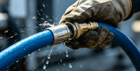
3. Hydraulic Hoses and Fittings: Flexible Yet Vulnerable

Hydraulic hoses and fittings are responsible for safely transferring pressurized fluid. Despite their apparent simplicity, hoses are frequent points of failure due to constant pressure, bending, vibration, and environmental factors.
Common failures include:
- Abrasion: Continuous rubbing against metal surfaces or other hoses causes external damage.
- Cracking and bulging: Exposure to UV, extreme temperatures, or aging can compromise integrity.
- Loose fittings: Incorrect torque during installation or system vibration can lead to leaks.
- Bursting: Occurs when pressure exceeds the hose rating, often due to system surges or blocked filters.
Preventive Measures:
- Inspect hoses for cracks, leaks, or worn spots regularly.
- Install protective sleeves or routing channels to reduce abrasion.
- Follow manufacturer torque specifications for fittings.
- Replace hoses at recommended intervals rather than waiting for visible wear.
Industry Example: Agricultural machinery often operates in dusty, rough environments. Hoses exposed to sunlight and sharp edges are particularly vulnerable. Using UV-resistant, reinforced hoses significantly extends service life.
4. Hydraulic Actuators: Cylinders and Motors
Hydraulic actuators, including cylinders and motors, convert hydraulic energy into mechanical movement. Failures in actuators can cause performance loss or even complete system shutdown.
Common actuator failures:
- Seal leakage: Reduces efficiency and contaminates the fluid.
- Rod corrosion or bending: Results from environmental exposure or mechanical overload.
- Internal wear: Continuous friction can degrade the cylinder or motor surfaces.
- Misalignment: Leads to uneven wear and premature failure.
Preventive Measures:
- Protect rods with covers or boots in harsh environments.
- Monitor and maintain proper load levels to prevent bending.
- Inspect seals and replace them proactively.
- Use clean hydraulic fluid to reduce abrasive wear.
Industry Example: In construction cranes, actuator failure can cause unsafe operations. Regular inspection and lubrication of rod surfaces prevent corrosion and extend operational life.
5. Hydraulic Filters: Small but Crucial
Hydraulic filters may seem minor, but they protect the system from contamination and maintain fluid integrity. Neglecting filters can result in system-wide failures.
Common filter issues include:
- Clogging: Leads to pressure drop, restricted flow, and pump cavitation.
- Bypass valve failure: Allows unfiltered fluid to circulate, causing contamination.
- Wrong specification: Using a filter not rated for the system’s pressure or flow reduces effectiveness.
Preventive Measures:
- Replace filters according to the manufacturer’s schedule.
- Select filters rated for the system’s flow and pressure.
- Monitor pressure drop across the filter to detect clogging early.
Practical Tip: In industrial presses and injection molding machines, clogged filters can significantly reduce production efficiency. Installing differential pressure gauges helps monitor filter status in real time.
Table: Common Failures and Preventive Measures for Hydraulic System Components
| Component | Common Failure Types | Preventive Measures | Typical Impact on System |
|---|---|---|---|
| Hydraulic Pump | Cavitation, wear, contamination | Fluid quality, filtration, pressure monitoring | Reduced flow, noise, potential damage |
| Hydraulic Valve | Leakage, sticking, pressure spikes | Cleaning, seal replacement, proper installation | Loss of control, safety hazards |
| Hydraulic Hose | Abrasion, cracking, loose fittings | Protective routing, inspection, correct torque | Fluid leaks, pressure loss |
| Hydraulic Actuator | Seal leaks, rod damage, internal wear | Preventive maintenance, load monitoring | Reduced motion, efficiency loss |
| Hydraulic Filter | Clogging, bypass failure, wrong specs | Scheduled replacement, correct specification | Contaminated fluid, pump damage |
How to Prevent Failures in Hydraulic System Components

Preventing failures requires proactive maintenance, proper component selection, and monitoring system parameters. Key practices include:
- Fluid Management: Maintain clean, high-quality hydraulic fluid and replace regularly.
- Routine Inspections: Check hoses, valves, actuators, pumps, and filters for wear or damage.
- Correct Installation: Use proper torque, alignment, and protection measures.
- Temperature Control: Avoid operating fluid above recommended temperatures.
- Pressure Management: Ensure relief valves and other pressure-limiting components are functioning correctly.
By understanding which hydraulic system components often fail, operators can implement preventive strategies, reducing downtime and extending component lifespan.
Conclusion
Hydraulic system components—pumps, valves, hoses, actuators, and filters—are all crucial for smooth operation. Awareness of common failure modes, combined with preventive maintenance and monitoring, is the key to system reliability. Correctly functioning pressure relief valves ensure maximum pressure is not exceeded, protecting all components. With proper care, hydraulic systems can deliver consistent, safe, and efficient performance over long periods.
FAQ
Q1: What are the basic components of a hydraulic system?
A1: The core components are pumps, valves, actuators, hoses/fittings, reservoirs, and filters. These work together to transmit power efficiently.
Q2: What component in a hydraulic system determines the maximum pressure?
A2: The pressure relief valve sets the system’s maximum pressure and prevents overpressure damage.
Q3: How often should hydraulic filters be replaced?
A3: Replace according to manufacturer recommendations or when pressure drop indicates clogging.
Q4: Can worn hoses cause pump failure?
A4: Yes, leaks or loose fittings reduce flow, leading to cavitation and pump damage.
Q5: How can valve sticking or leakage be prevented?
A5: Clean regularly, replace worn seals, and ensure proper installation.