Key Takeaways
- Hydraulic lines design is a core engineering discipline in fluid power transmission systems
- Pressure, flow rate, and material selection directly determine system efficiency and safety
- Steel tubes, rubber hoses, and PTFE lines serve different industrial applications
- International standards such as ISO 4413 and SAE J517 define safety and performance benchmarks
- Improper routing and sizing account for more than 60% of hydraulic system failures
- Smart hydraulic monitoring systems are transforming predictive maintenance strategies
- Lifecycle cost is significantly more important than initial installation cost
Introduction
In modern mechanical engineering, hydraulic lines design has evolved from a basic piping layout task into a highly specialized engineering discipline involving fluid dynamics, materials science, and system safety optimization.
Hydraulic systems are widely used in:
- Construction machinery
- Industrial automation
- Aerospace systems
- Energy infrastructure
- Marine and offshore engineering
According to Global Hydraulic System Market Reports (2026 outlook):
- Market size exceeds USD 45 billion
- Expected CAGR: 5.2%–6.8%
- Over 70% of heavy machinery relies on hydraulic systems
This makes hydraulic line design a critical factor influencing global industrial productivity.
Table of Contents
Hydraulic Lines Design Engineering System Architecture

Hydraulic Lines Design System Concept
A hydraulic line system consists of:
- Pressure lines
- Return lines
- Control lines
- Auxiliary circuits
Each line must be designed to handle:
- Pressure load
- Flow velocity
- Temperature variation
- Mechanical vibration
Fluid Transmission Engineering Principle
Hydraulic fluid follows Bernoulli-based flow behavior, where:
- Pressure decreases with increased velocity
- Friction losses increase with line length
- Diameter directly affects flow resistance
Engineering Insight
A 10% reduction in inner diameter can increase pressure loss by up to 30–40% in high-flow systems.
Hydraulic Lines Design Material Engineering Deep Analysis
Steel Hydraulic Lines Engineering Concept
Steel tubing is used in high-pressure fixed installations.
Performance Characteristics
- Pressure rating: up to 6000+ psi
- Excellent fatigue resistance
- Minimal volumetric expansion
Used in:
- Excavators
- Industrial presses
- Steel mills
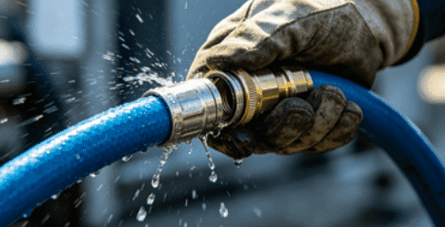
Rubber Hydraulic Lines Engineering Concept
Rubber hoses are flexible solutions designed for dynamic systems.
Performance Characteristics
- High vibration absorption
- Easier installation
- Moderate pressure rating (up to ~3000 psi typical industrial use)
Used in:
- Mobile cranes
- Agricultural machinery
- Automotive systems
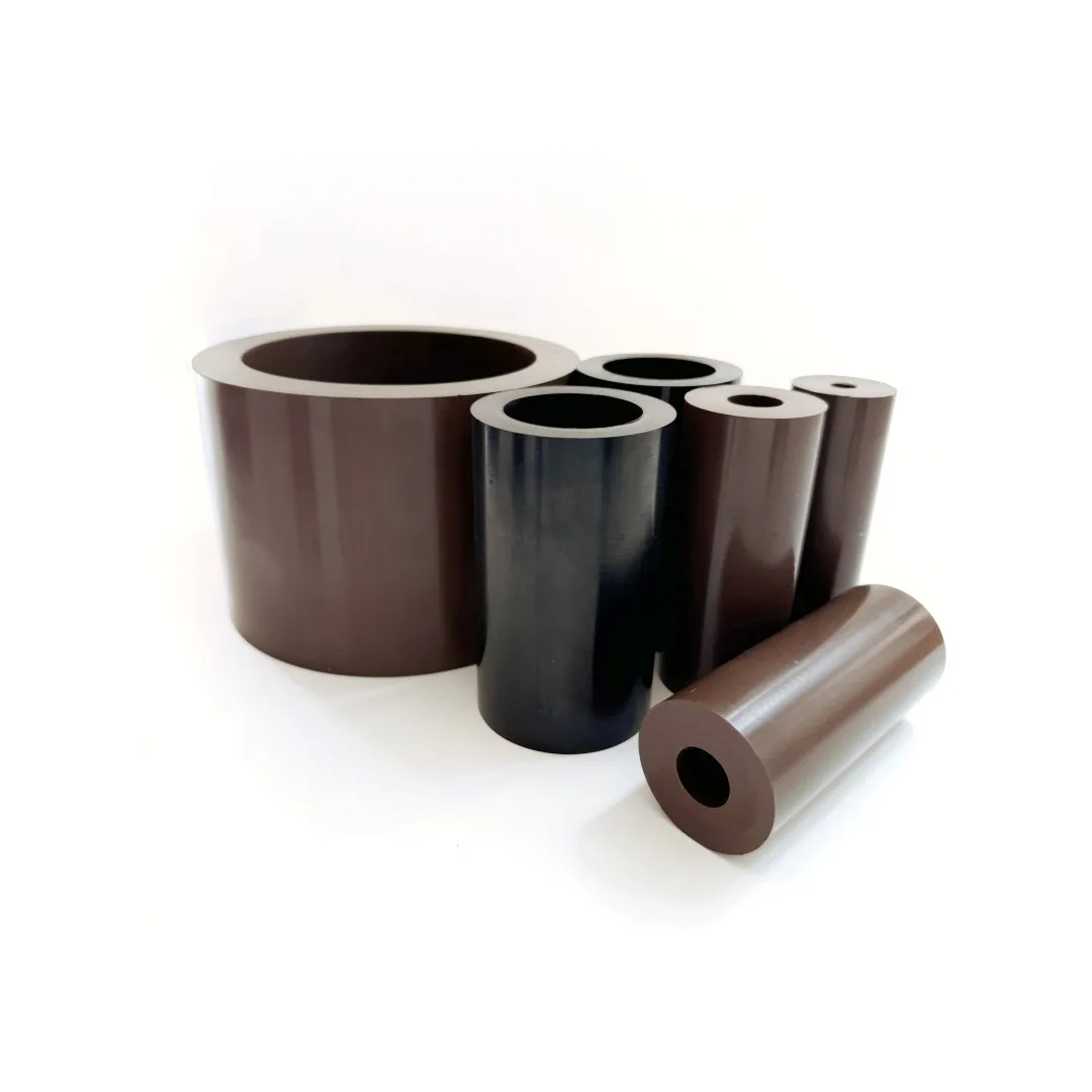
PTFE Hydraulic Lines Engineering Concept
PTFE systems are used in extreme chemical or thermal environments.
Performance Characteristics
- Temperature range: -100°F to +500°F
- High chemical resistance
- Low friction coefficient
Used in:
- Chemical plants
- Aerospace systems
- High-purity fluid transfer
Hydraulic Lines Design Flow & Pressure Engineering Model
Pressure Loss Calculation Concept
Pressure loss is influenced by:
- Pipe diameter
- Flow velocity
- Line length
- Fluid viscosity
Engineering Insight
Longer and narrower hydraulic lines significantly increase system energy loss.
Flow Velocity Design Concept
Recommended flow velocity ranges:
- Suction lines: 1–2 m/s
- Pressure lines: 3–6 m/s
- Return lines: 2–4 m/s
Exceeding these ranges increases:
- Heat generation
- Cavitation risk
- Component wear
Hydraulic Lines Design Standards Engineering Framework
Global Hydraulic Standards Table
| Standard | Organization | Function |
|---|---|---|
| ISO 4413 | ISO | Hydraulic system safety rules |
| ISO 1219 | ISO | Hydraulic symbols and diagrams |
| SAE J517 | SAE | Hydraulic hose specification |
| DIN 20066 | DIN | Installation guidelines |
| ISO 8434 | ISO | Tube fitting standards |
Engineering Compliance Insight
Non-compliant hydraulic systems have:
- 2–3x higher failure probability
- Increased maintenance downtime
- Reduced system efficiency
Hydraulic Lines Design vs Hydraulic Hose Systems
Engineering Comparison Matrix
| Feature | Hydraulic Lines | Hydraulic Hoses |
|---|---|---|
| Pressure Capacity | Very High | High |
| Flexibility | Low | Very High |
| Installation Cost | High | Medium |
| Maintenance | Low | Medium |
| Vibration Resistance | Low | High |
Engineering Decision Insight
- Hydraulic lines → fixed industrial infrastructure
- Hydraulic hoses → mobile and vibration systems
Hydraulic Lines Design Installation Engineering Guidelines
Installation Engineering Concept
Proper installation ensures:
- Leak-free operation
- Reduced vibration fatigue
- Stable pressure transmission
Engineering Best Practices
1. Clamp Optimization
Proper spacing reduces vibration-induced fatigue failure.
2. Bend Radius Control
Avoid tight bends to prevent flow restriction.
3. Contamination Control
Even microscopic particles can damage valves and seals.
Hydraulic Lines Design Failure Mode Engineering (FMEA Deep Dive)
Common Failure Modes
1. Seal Leakage Failure
Caused by improper torque or aging seals.
2. Burst Failure
Triggered by overpressure or material fatigue.
3. Vibration Fatigue Failure
Occurs in mobile machinery under constant motion.
4. Corrosion Failure
Chemical exposure weakens metal structure over time.
Failure Probability Insight
Studies show:
- 45% failures = improper installation
- 30% failures = material mismatch
- 25% failures = maintenance neglect
Hydraulic Lines Design Industry Application Engineering Systems
Construction Machinery Systems
Used in:
- Excavators
- Bulldozers
- Loaders
Function:
- Force transmission
- Hydraulic cylinder control
Industrial Manufacturing Systems
Used in:
- Hydraulic presses
- Injection molding machines
Requirement:
- High pressure stability
- Continuous operation
Energy and Offshore Systems
Used in:
- Drilling rigs
- Offshore platforms
Requirement:
- Corrosion resistance
- High-pressure endurance
Hydraulic Lines Design Digital Transformation (Smart Hydraulics)
Smart Monitoring Concept
Modern hydraulic systems integrate:
- Pressure sensors
- Temperature sensors
- Flow rate monitoring
- AI predictive analytics
Predictive Maintenance Concept
Benefits include:
- 30–50% reduction in downtime
- Early failure detection
- Optimized maintenance scheduling
Hydraulic Lines Design Real Engineering Case Studies
Case Study 1: Mining Excavator Fleet Optimization
Problem:
Frequent hydraulic line failures due to vibration.
Solution:
Upgraded routing + reinforced steel tubing.
Result:
- 42% reduction in failures
- 28% increase in uptime
Case Study 2: Industrial Press System Upgrade
Problem:
Pressure instability in long hydraulic lines.
Solution:
Optimized diameter and reduced line length.
Result:
- Improved pressure stability by 35%
- Reduced energy consumption
Case Study 3: Offshore Drilling Platform
Problem:
Corrosion and leakage in harsh saltwater environment.
Solution:
PTFE-lined hydraulic lines.
Result:
- 60% increase in system lifespan
- Significant reduction in maintenance cost
Hydraulic Lines Design Cost Engineering Model
Lifecycle Cost Structure
| Cost Type | Share |
|---|---|
| Material | 30–50% |
| Installation | 20–30% |
| Maintenance | 20–40% |
| Downtime Cost | High in critical systems |
Engineering Insight
Lifecycle cost can be 4–8 times higher than initial installation cost.
FAQ
What is hydraulic lines design in engineering?
It is the process of designing fluid transmission systems for hydraulic machinery.
Which material is best for hydraulic lines?
Steel for high pressure, rubber for flexibility, PTFE for chemical environments.
What causes hydraulic line failure most often?
Improper installation and excessive pressure are the leading causes.
How is hydraulic line diameter selected?
Based on flow rate, velocity limits, and pressure requirements.
Are hydraulic lines better than hoses?
They are better for fixed high-pressure systems, while hoses are better for flexible applications.
Conclusion
The future of hydraulic lines design is moving toward:
- Smart monitoring systems
- Higher pressure efficiency
- Lightweight high-strength materials
- AI-driven predictive maintenance
As industrial systems become more complex, hydraulic line engineering will remain a critical discipline ensuring safety, efficiency, and long-term operational stability across global industries.